Ray Tracing vs Rasterization
Conventional 3D rendering has typically used a process called rasterization since the 1990s. Rasterization uses objects created from a mesh of triangles or polygons to represent a 3D model of an object. The rendering pipeline then converts each triangle of the 3D models into pixels on a 2D image plane. These pixels may then be further processed or “shaded” before final display on the screen. While rasterization can be extremely efficient for producing images in real-time, adding realistic lighting effects to a rasterization pipeline adds complexity, requiring many hand-tuned parameters based on a given scene. Maintaining good performance usually requires using short-cuts or estimations, which can affect overall realism. Ray tracing represents an important step to achieving greater realism.
Ray tracing generates highly realistic images by simulating the physical behavior of light. Ray tracing calculates the color of pixels by tracing the path that light takes traveling from the eye of the viewer through the virtual 3D scene. Light may reflect from one object to another (causing reflections), be blocked by objects (causing shadows), or pass through transparent or semi-transparent objects (simulating translucency or dielectrics like glass or water) as it traverses the scene. All of these interactions combine to produce the final color of a pixel displayed on the screen. Fidelity can remain uncompromised, as shown in figure 1, and algorithms can be elegantly implemented, at the cost of massively complex computational workload.

How Does Ray Tracing Work
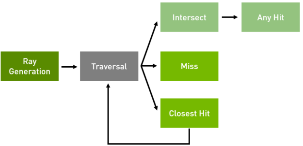
Ray tracing directly simulates light traveling through a virtual environment. Figure 2 shows how the environment consists of a camera, set of lights, 3D geometric models, and material descriptions of these models. Rays, representing light paths or photons, are then traced to determine what light value is seen by the camera sensor in a given direction. Tracing a ray typically follows a natural sequence of events:
- A ray is created representing a light path from the environment to the camera in reverse.
- The ray intersects the scene, determining which object the ray hits, if any.
- The material shader or environment shader compute the lighting value is along the ray’s path
- Finally, the resulting lighting value is written into a framebuffer.
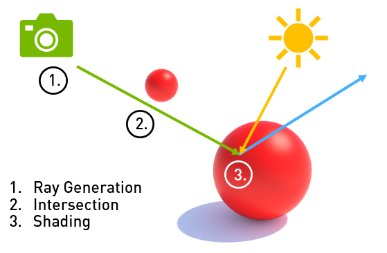
Step 3 is often performed by spawning additional rays to determine what the incoming light is at a point on an object, making ray tracing a naturally recursive algorithm.
Ray Tracing on the GPU
The ability to create truly photo-realistic imagery is why ray tracing has been heralded as the future of computer rendering. Ray tracing renderers today dominate virtual effects production and feature animation. The advent of massively parallel GPUs now expands the domain space in which ray tracing can be used. Offline rendering using GPUs now takes minutes as opposed to the hours required using mainstream CPUs. NVIDIA GPUs paired with NVIDIA’s state-of-the-art ray-tracing technology stack now provide the compute capability and software framework to execute interesting, real-time ray tracing workloads on consumer class workstations.
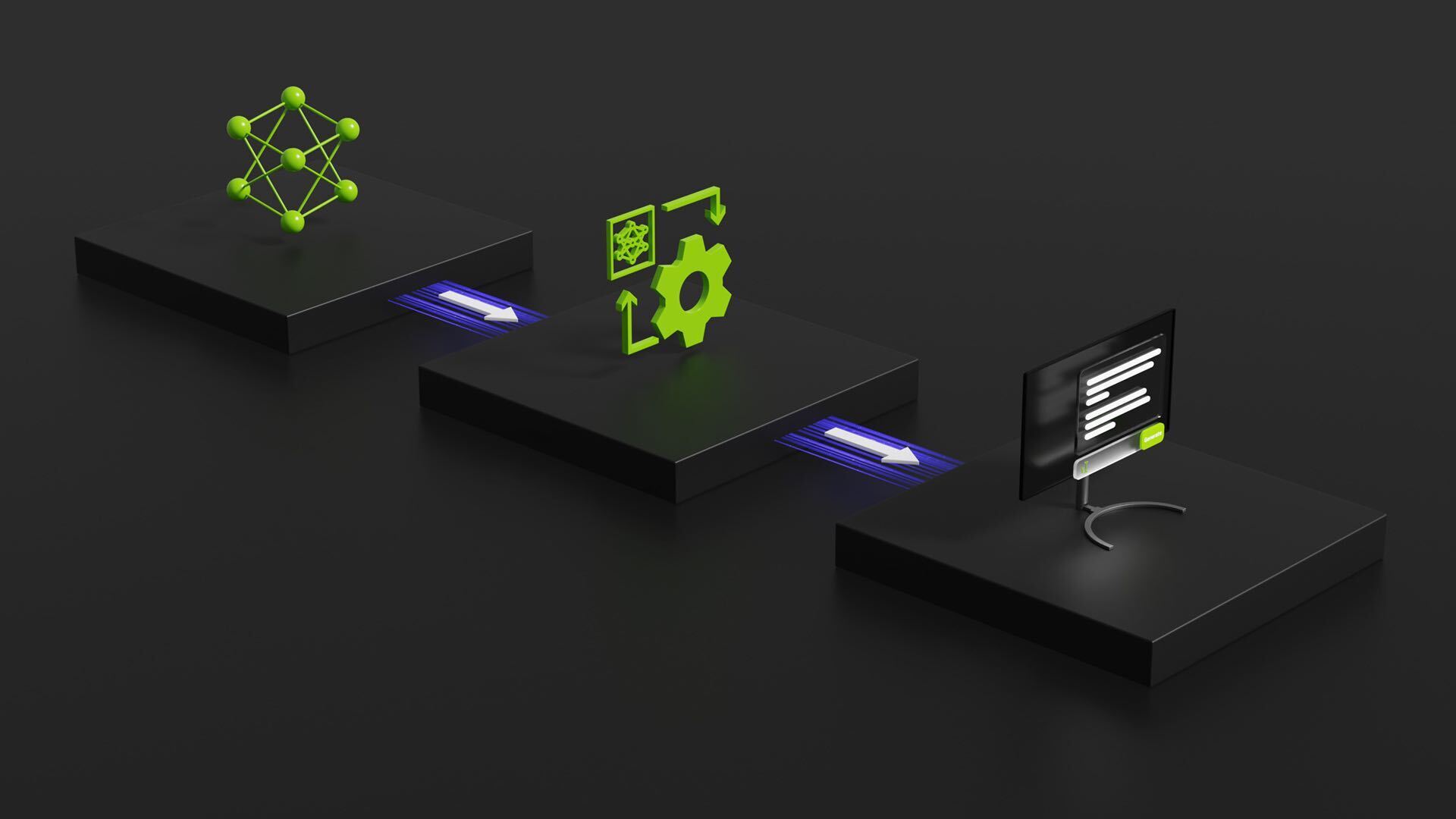
NVIDIA announced support for RTX technology on the new Quadro® GV100 this week at GTC. Developers can access NVIDIA RTX technology through multiple APIs, depending on their needs and development environment, shown visually in figure 3.
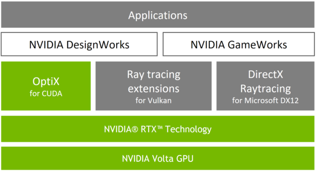
- Microsoft’s DirectX Raytracing (DXR) API. Fully integrates ray tracing into DirectX, an industry standard API used by game developers, making ray tracing a companion to rather than a replacement for rasterization and compute. DXR focuses on enabling real-time use cases via hybrid rasterization-ray tracing techniques.
- NVIDIA’s Vulkan Ray Tracing Extensions. Available soon; ray tracing extensions to the Vulkan graphics standard. Another path to tightly coupled ray-tracing and rasterization techniques in a cross-platform API.
- NVIDIA’s OptiX API. An application framework for achieving high performance ray tracing on the GPU. It provides a simple, recursive, and flexible pipeline for accelerating ray tracing algorithms. The OptiX SDK includes two major components which can be leveraged independently from one another: the ray-tracing engine for renderer development and a post-processing pipeline for image processing before display.
All three APIs share a common approach to describing ray tracing operations, making it straightforward for developers to access RTX across multiple platforms. A decade’s worth of investment in rendering software and hardware has lead to highly optimized ray tracing solutions, enabling previously unattainable levels of performance and interactivity. NVIDIA has also heavily invested in the development toolchain, making GPU programming, debugging, and profiling easier than ever.
For more information on DXR, check out our blog post on the topic. A preview of the Vulkan extensions is available in session S8521 at GTC this year. Now let’s turn to the OptiX API.
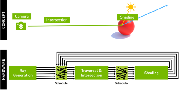
NVIDIA designed the OptiX API to fill this gap between the simple conceptual model and the relatively advanced execution model on NVIDIA GPUs, allowing developers to focus on their core ray-tracing algorithms, as figure 5 shows. OptiX builds on the key observation that most ray tracing algorithms can be implemented using a small set of programmable operations. OptiX provides an API for describing the virtual environment and a small set of user-programmable shaders to implement each phase of the ray tracing cycle.
The core of OptiX is a domain-specific just-in-time compiler. The compiler generates custom ray-tracing kernels by combining user-supplied programs for ray generation, material shading, object intersection, and scene traversal. High performance is achieved by using a compact object model and ray-tracing compiler optimizations that map efficiently to the new RTX Technology and Volta GPUs.
OptiX supports a wide variety of use cases, including interactive rendering, offline or batch rendering, collision detection systems, artificial intelligence queries, and scientific simulations such as sound propagation or neutron transport. OptiX has been integrated into a variety of currently available commercial software products and has been a key ray tracing SDK for nearly a decade.
Key benefits of using OptiX include:
- A programmable GPU-accelerated ray-tracing pipeline, easily customized to your application needs
- A single-ray programming model offering full support for recursion and a dynamic dispatch mechanism similar to virtual function calls
- State-of-the-art data structures for extremely fast ray-object intersection
- Support for rendering large scenes, made possible by transparent scaling across multiple GPUs and by automatic combination of multiple GPU’s memory over NVLink
- OptiX leverages the latest GPU architectural features without requiring application-side changes
- An AI-based denoiser to improve the user experience in real-time exploration
- Flexibility supports arbitrary shading models, including an example implementation of the physically based MDL material specification
- Comprehensive programming guides, reference documentation, and examples to help you quickly integrate OptiX into your applications
- An intuitive interface to NVIDIA’s RTX Technology and the power of Volta GPUs
Ray-Generation Programs
The first ray segment in a ray path, often referred to as the primary ray, uses the ray-generation program. This traces the ray through the scene, writing results from the trace into an output buffer. Below is a very simple example ray-generation program.
// The user can define an arbitrary struct to carry data associated with a ray
// and to return values from the trace.
struct PerRayData
{
    float4 result;                                        // Output variable for results.  We could track other
                                                          // information here as needed.
};

rtDeclareVariable(CameraParams, camera_params, , );       // Input parameters describing
                                                          // the camera model.
rtDeclareVariable(rtObject,     scene_root_group, , );    // The top level group
                                                          // containing scene description.
rtBuffer<float4, 2> output_buffer;                        // Output buffer to store rendered
                                                          // image.

rtDeclareVariable(uint2, launch_index, rtLaunchIndex, );  // OptiX built-in variable containing
                                                          // the current index into launch grid.
                                                          // Usually this corresponds to pixel
                                                          // index in the output image.
rtDeclareVariable(uint2, launch_dim,   rtLaunchDim, );    // OptiX built-in variable containing
                                                          // the size of the launch grid. Usually
                                                          // this corresponds to the dimensions
                                                          // of the output image.


RT_PROGRAM void pinhole_camera()
{
    // Create a primary ray by modeling a pinhole camera. Alternatively we could read
    // pre-generated rays from an input buffer or use some other method.
    const float3 ray_origin = pinholeCameraGetOrigin(camera_params);
    Const float3 ray_direction = pinholeCameraComputeDirection(camera_params, launch_index,
                                                               launch_dim);
    optix::Ray ray = optix::make_Ray(
          ray_origin,             // camera position
          ray_direction,          // direction from origin to pixel position on screen plane
          0u,                     // ray-type (see documentation)
          scene_epsilon,          // minimum intersection distance
          RT_DEFAULT_MAX);        // maximum intersection distance

    // Initialize our per-ray data structure and call the built-in function rtTrace
    PerRayData prd;
    prd.result = make_float4(0.0f);
    rtTrace(top_object, ray, prd);

    // Write results into buffer.  Once a launch is finished, this output buffer is typically
    // drawn to the screen or written to an image file.
    output_buffer[launch_index] = prd.result;
Scene Traversal Programs
OptiX utilizes state-of-the-art spatial partitioning hierarchy data structures, allowing for very fast culling of portions of the virtual scene not intersected by a given ray. The Optix core compiler controls creation and traversal of these data structures. This allows OptiX to hide the complexity of highly optimized, architecture-specific implementations and leverage years of NVIDIA research into traversal acceleration structures.
Intersection and Bounding Box Programs
Custom primitives such as spheres, curves, or subdivision patches can be implemented employing user-defined intersection and bounding box programs. The bounding box program must calculate an object-space axis-aligned bounding box for a custom primitive. The intersection program returns true or false based on whether an input ray intersects the primitive. Below are simple examples of each type of program demonstrating how a sphere primitive might be implemented.
rtDeclareVariable(float4, sphere, , );                     // Input variable giving sphere center, radius

rtDeclareVariable(float3, normal, attribute normal, );     // Attribute variables allow data passing from intersection
                                                           // program to hit programs

rtDeclareVariable(optix::Ray, ray, rtCurrentRay, );        // Built-in variable provided by OptiX

RT_PROGRAM void intersect_sphere()
{
    float3 center = make_float3(sphere);                   // Extract sphere’s center position
    float  radius = sphere.w;                              // Extract sphere’s radius

    float3 n;                                              // Output parameter for the surface normal
    float  t;                                              // Output parameter for the intersection distance

    if(intersect_sphere(ray, center, radius, n, t))        // Determine if the ray hits the sphere and, if so,
                                                           // at what distance
    {
        if(rtPotentialIntersection(t))                     // Tell OptiX that the ray intersects the sphere.  OptiX
                                                           // will check if the intersection distance lies within the
                                                           // current valid ray interval and return true/false
                                                           // accordingly.

        {
            normal = n;                                    // Output attributes are always written to between
                                                           // rtPotentialIntersection and rtReportIntersection

            const int material_id = 0;
            rtReportIntersection(material_id);             // Report intersection with material ID
        }
    }
}

// Takes primitive index for use with multi-primitive Geometries (eg, triangle meshes)
RT_PROGRAM void bounds (int /*primitive_index */, float result[6])
{
    const float3 center = make_float3( sphere );
    const float  radius = make_float3( sphere.w );

    optix::Aabb* aabb = (optix::Aabb*)result;              // Cast float array to helper data type for ease of use
    aabb->m_min = center - make_float3(radius);
    aabb->m_max = center + make_float3(radius);
   }
Closest-Hit and Any-Hit Programs
The closest- and any-hit programs work together to function as a material shader. OptiX allows the developer to specify one or more types of rays (e.g., radiance, ambient occlusion, or shadow rays). A material can specify a closest hit and any-hit program to describe shading behavior when an object is intersected for each ray-type. Hit programs receive information from the intersection program via attribute variables. They pass information back to the ray generation program by writing into the ray payload.
Closest-hit programs are invoked when the ray tracing core has fully traversed the scene and found the closest intersection within the current ray’s valid distance interval. Final shading typically occurs at this stage. A full-featured shading system might evaluate physically based reflection functions and generate secondary rays to evaluate reflections, refractions, and light occlusion.
Any-hit programs get invoked any time a new potentially closest object is found while traversing the scene. Any-hit programs can take one of three actions on the current potential intersection:
- The intersection can be ignored by calling
rtIgnoreIntersection. This can be done to reject an intersection in cases such as transparent alpha cutouts. - Ray-traversal can be terminated by calling
rtTerminateRay. This is often used in point-to-point visibility tests since any object found between the points is sufficient. - The intersection can be accepted, but traversal is continued. This is the default behavior if neither
rtIgnoreIntersectionorrtTerminateRayis called.
Either the any-hit or closest-hit program may be left unbound for any given material ray-type slot. For instance, an opaque material might only require an any-hit program for shadow rays, since finding any intersection between a light and a shading point is sufficient to determine that a point is in shadow. On the other hand, opaque materials usually have only a closest-hit program bound for radiance rays.
Below is an example of a very simple pair of hit programs for an opaque material which shades objects by simply visualizing their surface normals.
// Often, any-hit and closest-hit programs use differing ray payload structs, depending on what data they want to
// return to the ray-generation program. For simplicity we will use a single type.
struct PerRayData
{
    float4 result;  // Radiance value for closest hit, shadow opacity for any-hit
};

rtDeclareVariable(PerRayData, prd, rtPayload,);         // Built-in providing access to this ray’s payload struct
rtDeclareVariable(float3, normal, attribute normal, );  // Attribute specified by our intersection programs

RT_PROGRAM void normal_shader_closest_hit_radiance()
{
    // Transform the object normal into world space and convert to a color
    const float3 world_space_normal = optix::normalize(rtTransformNormal(RT_OBJECT_TO_WORLD, normal));
    Const float3 color_normal = world_space_normal*0.5f + 0.5f;
    prd.result = make_float4(color_normal, 1.0f);
}

RT_PROGRAM void normal_shader_any_hit_shadow()
{
    // this material is opaque, so it fully attenuates all shadow rays
    prd_shadow.result = make_float3(0.0f);

    // We terminate this ray since we only want to know if any geometry is hit, not the closest
    rtTerminateRay();
}
Miss Programs
If no geometry is hit by a ray, a miss program is invoked. A miss program can be specified per ray-type and may be left unbound. Miss programs are used to implement environment maps or infinitely distant backgrounds. Below is a program implementing a user-specifiable constant colored background environment.
struct PerRayData
{
    float4 result;  // Radiance value for closest hit, shadow opacity for any-hit
};

rtDeclareVariable(float4, bg_color, , );             // Input variable for the background color

rtDeclareVariable(PerRayData, prd, rtPayload, );     // Built-in providing access to this ray’s payload struct

RT_PROGRAM void miss()
{
    prd_radiance.result = bg_color;
}
Performance
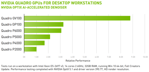
OptiX runs on a range of NVIDIA GPUs, but achieves best performance using a Volta GPU, as figure 6 shows.
Enhancing Creativity with NVIDIA OptiX
Rendering software that uses NVIDIA OptiX, such as Autodesk Arnold, Chaos Group V-Ray, Isotropix Clarisse, Optis, Pixar RenderMan, and Solidworks Visualize will automatically use RTX technology when running on the NVIDIA Volta architecture.
The OptiX AI denoising technology combined with the new NVIDIA Tensor Cores in the Quadro GV100 and Titan V deliver 3x the performance of previous generation GPUs and enable noiseless fluid interactivity for the first time.
NVIDIA is transforming rendering—and the entire design process. Enabled by NVIDIA Volta GPUs and NVIDIA® RTX™ ray tracing technology, you can enhance your creativity with real-time, cinematic-quality rendering for better results and immediate decision making. Explore designs with your client in the room, experiment with lighting and materials as you accurately simulate real-world lighting conditions interactively.
If you’d like to learn more about OptiX, you can find more information on the NVIDIA OptiX developer page, which includes links to detailed documentation and how to obtain OptiX.